360 VR STITCHING WITH PTGUI FOR BEGINNERS |
|
This beginner's guide has been written to help those unfamiliar with PTGui to stitch fisheye images to produce a complete 360x180 panorama image that can be viewed in a spherical viewer. Although using a Windows XP platform for the examples, MAC users should have little difficulty in following the workflow. I have used PTGui Pro V7.5 here, but the standard version will do just as well. The trial version will be fine, too.
|
|
INSTALLATION I will assume you are working on a Windows PC. Download and run the PTGui V7 setup program from http://www.ptgui.com . Download Smartblend (an alternative blender) from http://wiki.panotools.org/SmartBlend and unzip to a folder of your choice. Smartblend is particularly useful for hiding some types of stitching errors by routing seams around features. It isn't available for MAC, so use PTGui's built-in blender instead. Launch PTGui. Click on Tools->Options and select the Plugins tab, and in the Smartblend section browse to the folder where you unzipped smartblend.exe to. Set the command line parameters to -w -MinSize 32 like this:
Autopano (alternative control point generator) and Enblend (another blender) would be installed in a similar manner, if required, but need not be installed just now. Likewise, the long established Panorama Tools programs can be installed and made use of by PTGui if required. Download from http://photocreations.ca/panotools/index.html when needed, and register their installed location on the Panorama Tools tab.
|
|
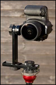
PREPARATION OF THE INPUT IMAGES For your first stitch, I suggest you use the sample set of fisheye images at www.johnhpanos.com/sigma8.zip (but by all means use your own if you prefer). Unzip these to a folder of your choice. These are five images taken with a Sigma 8mm f/3.5 circular fisheye lens on a Canon 20D DSLR. The camera was mounted on a Nodal Ninja 3 spherical panorama head and its position adjusted so that the camera rotated about the entrance pupil of the lens to avoid parallax effects. There are four shots taken around at 90 degree intervals with the camera level, plus a zenith shot taken with the camera pointing vertically up. The images were shot in RAW format, and the jpeg images were generated with Adobe Camera Raw (ACR) in Photoshop CS2. The images were rotated into portrait orientation for viewing convenience (i.e. right way up) and corrected for chromatic aberration and slight vignetting in ACR. Normally, I would recommend that you generate tiff images rather than jpeg for maximum quality.
|
|
START A NEW PTGUI PROJECT Launch PTGui and select the Project Assistant tab. Click on the Load Images button and browse to your images. Select only the first five (four horizontals + zenith) and click on Open. The images will be added to the project and the Lens Data panel appears. Click on ok to accept the lens data retrieved from the exif data in the image files. You will then have this display:
The lens data confirms that we are using a circular fisheye with a field of view of 180 degrees. Use the Circular selection whenever the whole or part of the edge of the image circle is visible in the image frame, as here. Use the Fullframe option when the image circle lies wholly outside the image frame, as would be the case for the Nikon 10.5mm fisheye on a DSLR with an APS-C size sensor. The horizontal field of view would then be around 87 degrees for an image opened by PTGui in portrait orientation. Here, we need to heed the reminder to crop our circular images by clicking on the link to the Crop Tab:
Adjust the circular selection to align with the inside edges of the visible parts of the image circle. You can drag the whole selection and also drag the top, bottom and sides. Select a diferent image if the edges are not clearly visible. (Earlier versions of PTGui had an Apply to All Images button which you should click. This is now the default action in V8). Then select the Project Assistant tab.
|
|
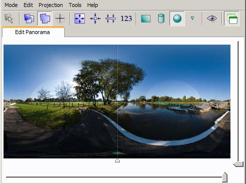
ALIGNING THE IMAGES Click on Align Images. This will add control points between overlapping images and the optimizer will be run to align matching control points in the images. Note that this process will be carried out on a spherical stitching surface, the intention being to reproduce the entire view as seen from the camera position. The Panorama editor window will appear. This shows the current state of the images in the output area. Click on Projection and select Spherical: 360x180 equirectangular to ensure the entire 360x180 stitching area is going to be output in our panorama.
There's an obvious stitching problem with the white painted edge on the right hand side. Why are the images not matching up? Well, turn your attention to the Project Assistant tab and click on the Control point assistant button. Click on Suggestions for improving the results to bring up the following:
For the horizontal shots (images 0-3), you want control points between images 0-1, 1-2, 2-3, and 3-0 so that you have a complete chain of images around the spherical stitching surface. But we are told that there are no points between 0 and 3, because the control point generator didn't work too well there. Nobody is perfect! So let's correct that deficiency by adding some control points by hand. ADDING CONTROL POINTS MANUALLY Exit the Control Point Assistant panel (click the corner "x") and then click on the Control Points tab. Select image 3 in the left hand window and image 0 in the right hand window. Set the zoom to 100%. Now find some matching features towards the bottom of the image in the white paint strip. Click once on a feature in the left hand window, and then click on the identical feature in the right hand window. That creates one control point, like this:
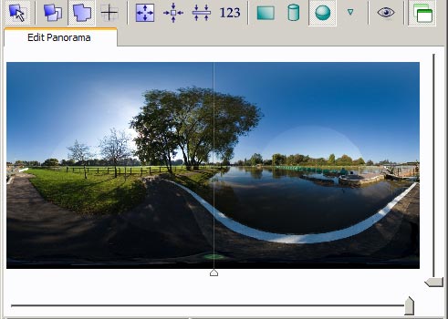
Note that you can fine tune the position of the marker after clicking on a feature by using the arrow keys on the keyboard. Alternatively, you can click on a point with ctrl and alt held down and drag the point accurately into position. Find some more features spread out vertically along the overlap area and add three or four more control points. Don't put points on anything likely to move between shots - like water surface features, clouds, people, vehicles, waving foliage etc. Now return to the Project Assistant tab and click the Optimize button. The optimizer will do its best to bring the images into alignment at the points made with control points. (It doesn't look at the actual image data). Accept the optimizer report and the Panorama Editor window should now show an improved alignment:
At this point we might be happy to accept this and go on to generate the output panorama. If we want to be picky, then we could investigate the current control point assignments, either visually on the control points tab or via the Control Point Table....
CHECKING THE QUALITY OF THE OPTIMIZATION RESULT You can display the Control Point Table via the green icon in the row at the top of the PTGui window or via the Control Point Assistant button:
The Index is the number of the control point within the set assigned between the two specified images. The distance value shows how well (or badly) the optimizer has done in getting the two marked features to align accurately. The distance (in pixels) would be zero for perfect alignment. (Click twice on the column heading to sort the list on that parameter). So here, point number 6 between images 2 and 4 is not aligned very well, with an alignment error of 10 pixels. If you double click on the item line, you will be taken to the Control Points tab where you can make a judgement on the likely cause of the misalignment and take appropriate action, or you can click on the GOTO icon at the top left. It turns out that this point is on some tree foliage - probably waving about in the wind. The point should be deleted or moved to a more solid feature. Other points can be checked similarly and dealt with. Periodically in the checking process, return to the Project Assistant tab and rerun the optimizer. Ideally, you want to see the maximum distance reported as no more than 3 or 4, but for your first stitching attempt you can be satisfied with whatever is shown and proceed to stitch the output panorama. However, it would be a good idea to first save your work by clicking File->Save As and create a project file. This can be opened with PTGui any time later to restore your project to the current state and continue with it. (The Save option is not available in the trial version).
|
|
GENERATING THE PANORAMA Click on the Advanced button (far right of the Project Assistant tab). Select the Create Panorama tab. Click Set optimum size and select Maximum. Set the remaining fields like this (specifying your own output folder and file name, of course):
Note that you can omit images from the stitch using the check boxes at bottom left. The Use fast transform option should not be selected when stitching together images that exactly butt together rather than overlapping. It's inclined to leave small holes at the pointy corners of images. Otherwise, it's quite safe to use the option to speed things up without impacting on image quality. So, finally, click on Send to Batch Stitcher (or on Create Panorama if using a trial version of PTGui) to generate the output panorama. After any post processing in Photoshop, the image can be resized and sharpened according to how the image is to be presented for viewing.
|
|
VIEWING THE STITCHED PANORAMA A good standalone viewer is FSPViewer, from www.fsoft.it/panorama/fspviewer.htm. If you select Tools->Options->Folders & Files in PTGui, you can specify this as the viewer for equirectangular images. The View button on the Create Panorama tab can then be used to display the panorama image just stitched very conveniently. To create a panorama in QTVR format (.mov), there's an option available to convert the equirectangular file on the Utilities menu or you can use a specialist program such as Pano2QTVR or Pano2VR from http://gardengnomesoftware.com/. For good quality full screen display, you will need an equirectangular image of a size between 5000x2500 and 6000x3000 pixels. DevalVR is another excellent viewer that is capable of displaying both equirectangular and .mov files, from http://www.devalvr.com/.
|
|
MORE ADVANCED STITCHING That is the basic semi-automatic process. You may well not get perfect results to begin with, and this introductory tutorial only gets you so far. You can intervene at all stages to attend to things manually via the tabs in advanced mode (click on the Advanced button in the Project Assistant tab). One problem not dealt with is that of the intrusive tripod at the nadir. This can either be hidden with a logo of some sort, or patched with a separate shot taken of the nadir area without the tripod in place. Another common problem is levelling. You may need to level the panorama to get the verticals properly upright and the horizon flat and level across the centre of the output area. This can be done by dragging the image in the Panorama Editor window (click on the “Edit entire panorama” button), or more accurately by following this tutorial: http://www.johnhpanos.com/levtut.htm . Tutorials are available for these and other topics. See the PanoTools wiki at http://wiki.panotools.org/ for further advice and guidance, as well as PTGui's own help pages.
Written by John Houghton
|
|