LEVELLING A PANORAMA IMAGE WITH PTGUI
|
|
This tutorial assumes that you have started a PTGui project and have got as far as obtaining a good optimization - i.e. established a good "fit" of the images, but the vertical features aren't truly vertical and the horizon snakes up and down somewhat. Fixing this is actually very easy in most cases and shouldn't take more than a couple of minutes. (You can also level a single stitched panorama image in a very similar way - see the final paragraph for details. Flash video demo here, or mp4 version here).
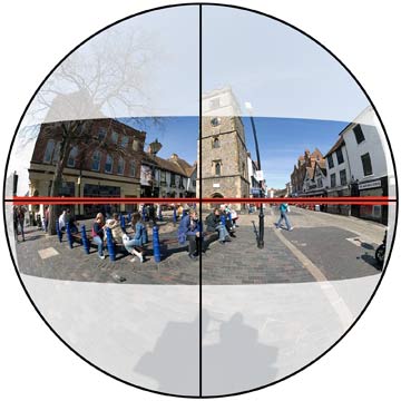
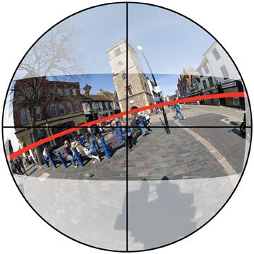
Why are the verticals not vertical? The cause of the bad alignment of the verticals and the horizon is that the stitched image is not in the optimum position on the stitching surface, which is a virtual sphere. So instead of the image being positioned so that the horizon in the image (red line) is aligned with the equator of the sphere (Fig 1), it's somewhere else (Fig 2).
|
|
Fig 1 |
Fig 2 |
The output image area (indicated by the clear area) is always centered on the point where yaw=pitch=0 degrees. You won't necessarily have taken sufficient images to cover the entire sphere, of course - just enough to cover the area of the required output view. So how do we get from the position in Fig 2 to Fig 1? There's more than one way to do this, but here we will use vertical line control points (known to Panorama Tools as t1 points). We make use of the fact that when the horizon is aligned with the equator of the sphere, the verticals will be aligned with lines of longitude (great circles passing through the poles). Lines of longitude will appear upright in cylindrical, equirectangular and rectilinear projections. And how do t1 points differ from ordinary control points? Well, it's all to do with how the optimizer treats them. For ordinary points, the optimizer will try to position images so the x,y coordinates of the corresponding marked features in overlapping images are as near as possible identical. For t1 points, the optimizer ignores the y (vertical) coordinates and simply tries to make the x (horizontal) coordinates equal. If the x coordinates of two points are equal, then they must lie on the same vertical line and are therefore vertically aligned. NB. Since PTGui V9.1.4, PTGui optimizer supports two different methods for handling horizontal line / vertical line control points. 'Level in second pass' first optimizes the panorama using the regular control points and then does a separate levelling step using the line-type control points. This is the method that was always used in previous versions. 'Include in single pass' will do a single optimization pass using all control points. This is the method used by the original Panorama Tools optimizer. However, the second pass levelling operation can alternatively be very conveniently performed independently of the optimizer by using Edit->Level Panorama on the Panorama Editor window. (Note that this different to the Straighten Panorama option, which takes no account of the image contents or control points).
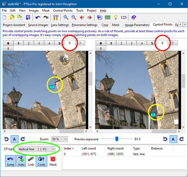
Assigning vertical line control points The first thing to do is identify some vertical edges in the output image, like edges of walls and doors. Then select PTGui's Advanced mode and go to the Control Points tab. You now want to set a t1 point at one end of a vertical edge in the left hand window, and at the other end of the same edge in the right hand window. You may need to have the same image displayed in both windows to do this, or the ends of the edge might be in different images. The procedure is the same: select control point type "Vertical line (t1)", click once in the left hand window on one end of the vertical edge, and then click on the other end of the edge in the right hand window - like this : |
|
|
|
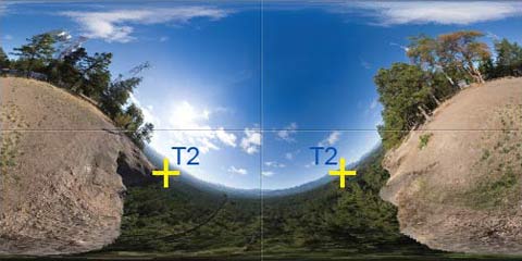
Understand that this illustrates a complete single vertical line control point. You don't click on the same feature in the two windows as you do for ordinary control points. Having created the t1 point on this, the first line feature, now find a second vertical edge (in the same or different images) and go through a similar process to create a new t1 point on that too. The idea is that when the optimizer aligns the images to get two or more vertical edges properly vertical, the horizon will be automatically horizontal and flat. Preferably choose edges separated by about 90 degrees of yaw - levelling won't work if the edges are exactly 180 degrees of yaw apart, as they will be on the same great circle. What happens then is that the two edges on the great circle become vertical, but there is nothing to stop the edges sliding up and down - i.e. around the circle. As the two edges slide round opposite each other on the circle, they remain aligned with the circle and both are therefore vertical, but vertical edges in the rest of the panorama will be at all sorts of angles as the whole panorama rotates. The optimizer will be happy with any of these positions as the requirement to make the t1 edges vertical is satisfied. The converse is also true: get the horizon horizontal and all the vertical edges will automatically become vertical. Horizontal line control points (type t2) can be assigned on horizontal features in a very similar way to get them horizontal. You need to be careful in using t2 points, though. In a cylindrical or equirectangular projection, only the straight line of the horizon is preserved; all other horizontals become curved so cannot be straightened/levelled in this way. The horizon will require more than one t2 point to straighten it. The reason is that if the horizon is curved, a single t2 point set on the two ends of the horizon can level the ends while the horizon still curves up or down in the middle. Like this:
(Remember, This is a single t2 point created by clicking on one end of the horizon in one window and on the other end in the other window). You should therefore have a second t2 point assigned on the middle of the curve and one end. The horizon will be flat and level when both t2 points have been aligned with the horizontal by the optimizer. Usually, you don't have a clear view of the horizon anyway so this is largely academic for much of the time.
Level the panorama All you need do now is go to the Panorama Editor window and use Edit->Level Panorama, which will complete the process. (NB. NOT the "Straighten Panorama" button, which does something different). Otherwise, you need to run the Optimizer. I've assumed that the lens parameters have already been optimized so all that's needed is to give the optimizer the freedom to slide the images about in order to get the t1/t2 points aligned. It's rather like sliding a baseball cap around on your head. The cap can be moved into all sorts of positions while retaining exactly the same overall shape. Likewise with the images on the stitching sphere. They all slide together as a single unit into a new position where all the t1 and t2 features are properly aligned. To do this, we need to allow the optimizer to vary yaw, pitch and roll on all images so they can take up any new position required. However, to keep the panorama image from shifting sideways (and thus undoing any centering already performed) you may optionally uncheck yaw on just one image to anchor it horizontally. The anchored image can still move up and down and rotate. So set the parameters like this and click on the Run Optimizer button:
|
|
|
|
A few points to note: 1. I selected image 0 as the anchor by unchecking its yaw parameter. Any other image would have done just as well. 2. You can run the optimizer, or just use Edit->Level Panorama on the Panorama Editor window. In the latter case, you don't need to set any particular parameters on the Optimizer tab, so it's obviously more convenient to do it that way. 3. t1 points are assigned on features that should be vertically aligned in the output image projection. While straight line features are obvious candidates for marking, don't overlook other features like reflections of objects in a level water surface, which are naturally vertically aligned. After optimization, the image should then be properly levelled.
|
|
|
|
Caution: If you should need to centre the final image after levelling, do not simply click the main centering button on the panorama editor window. This centers both horizontally and vertically, which will destroy the levelling. Instead, right click on the button and select the horizontal centering option . This only moves the image sideways and preserves the vertical positioning
Levelling a single stitched panorama image A finished stitched image can be levelled in just the same way. You will need an uncropped copy of the image, i.e. exactly as it was output by the stitcher. If blank areas have been cropped away, then restore the cropped areas as best you can. Start a new PTGui project and add the image, specifying the lens type and hfov to match the output panorama projection type and fov in the original project file. E.g. For a 360x180 VR image, specify lens type equirectangular and hfov 360. Set the other lens parameters all to 0. Set the output panorama image parameters the same as for the input image and set the size to be the optimum (maximum). Follow the instructions detailed above to assign t1 points and perform the levelling, and then generate the output image. See flash video tutorial for a 360x180 example, (or mp4 version here) |
|
John
Houghton |
|